3D modeling and CAD design

The 6NAPSE Group produces 3D modeling for manufacturers. Our means allows to pass from the concept to the physical part being necessarily based on digital models, the use of CAD design becomes essential.
The 6NAPSE Group may have several types of design to carry out for its customers:
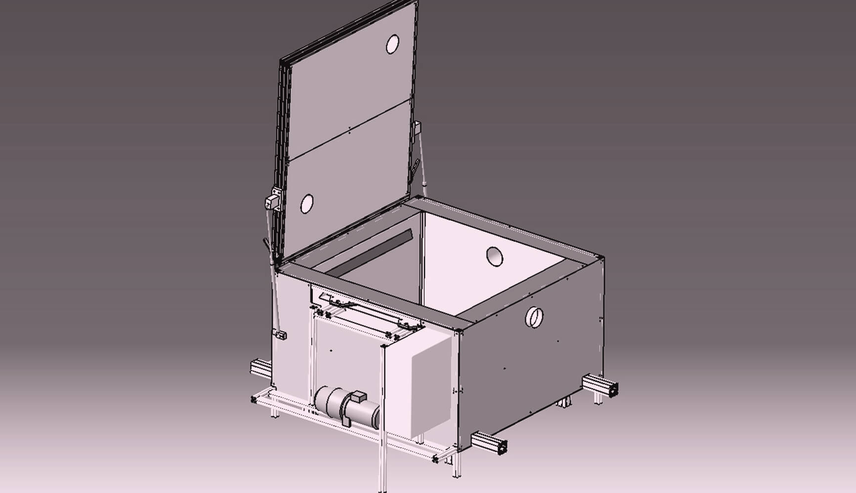
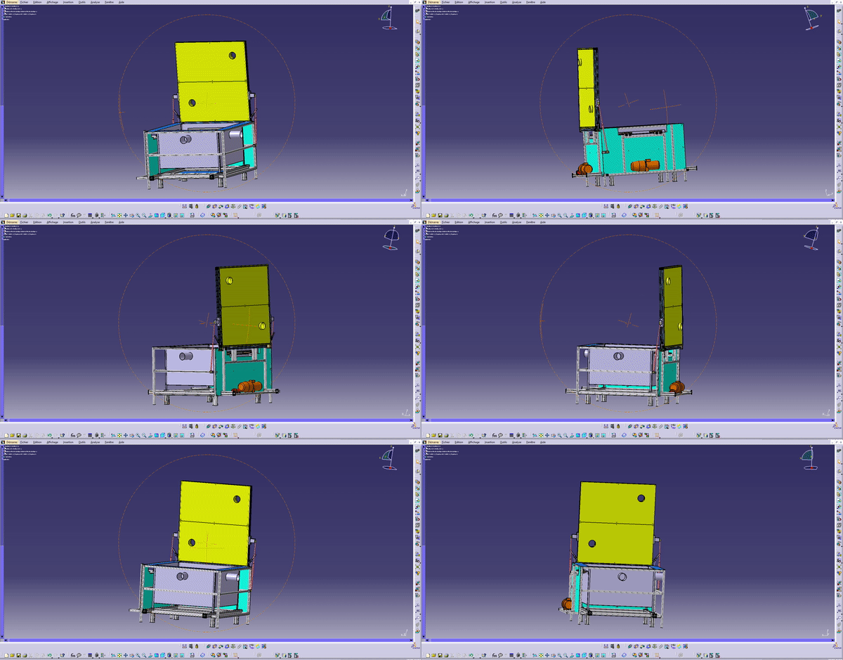
- Test frames (e.g. in the context of vibration endurance tests) which are made to measure taking into account the various constraints of mass, dimensions, resonance frequencies, etc.
- Tailor-made test benches: in particular for the control of products at the end of the production chain or for the production of acoustic boxes.
- Production support tooling (e.g. shock absorber compressor for the automotive sector)
These designs affect all industrial sectors that may have these needs (automotive and in particular equipment manufacturers, aeronautics, electronics, etc.).
Computer Aided Design (CAD)
Computer Aided Design (CAD) is an IT tool used during the design process of a product. The purpose of CAD is to allow the designer to digitally draw a model of his part or the assembly he wishes to make using CAD software (eg CATIA, Solidworks, CREO, Fusion 360, etc.). ).
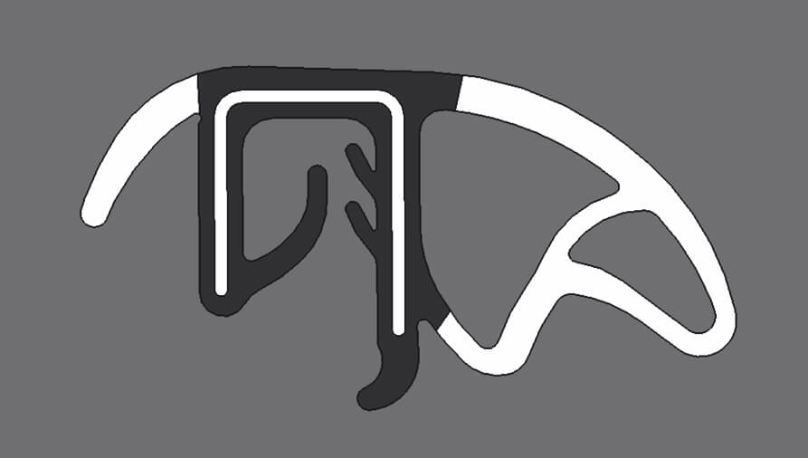
The 3D model consists of two elements: the 3D model which is the visual representation of the part to be designed, and the design tree, which displays and details all the stages and modifications of the model. This design tree is very useful because it allows you to find each point to modify it later in the model. Most CAD software also offers a standardized drawing solution. These plans represent the final stage of the design. Indeed, they indicate all the dimensions and all the dimensional tolerances necessary for the production of the part in the machining center.
CAD comes after a study phase of the different constraints that will be applied to the part to be created. This study makes it possible to size the part after having chosen the material in which it will be made.
3D models of parts assembly
Some products are assemblies requiring multiple parts. It is therefore necessary to be able to place the different parts relative to each other and allow them movement or not. Thus, the constraint tools define mechanical connections in a product composed of several parts following the movement or on the contrary the fixing that one seeks to obtain. In addition, some software makes it possible to implement motion simulations from an assembly whose constraints are defined.
The advantages for manufacturers of CAD design
For all manufacturers, the use of CAD saves considerable time for the transition from design to manufacturing (compared to the drawing carried out by hand a few years ago).
Added to this is reduced development costs and much greater accuracy.
In addition, CAD softwares have more and more tools to ensure optimal assembly of the parts making up an assembly, once they have been manufactured (control of interferences and clearances, etc.).
Finally, the constant evolution of the industrial world sees an increasing use of additive manufacturing in the prototyping phase.
How our teams create the CAD of a part or an assembly
1. Sketch
To make the 3D model of a part, the designer define the shape on a sketch from which the material will be added. This step is repeated on each new material addition to the model.
2. Material removal
Similarly, it may be necessary to remove material (grooves, holes, pockets, grooves). For this, we also use a sketch to determine the position and shape of the removal of material to be performed.
3. Accurate model
Once the desired shape is obtained, the designer refines the model with the necessary chamfers, fillets, taps and threads.
4. Validation of the model
Finally, he can then present the model to validate the realization or rework it on certain specific points. Once the model has been validated on all sides, the designer can proceed to the drawing and place an order.
In the case of assemblies of several parts, the model is called a “product” and its design tree will have for branch the design trees of each of the parts present in the assembly. To this must be added all the constraints linking the parts together.
6NAPSE group assets
The advantages of producing CAD via the 6NAPSE teams are multiple:
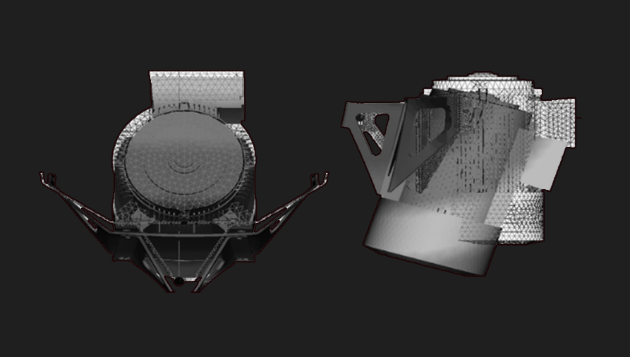
- The possibility of performing numerical simulations directly on these designs in order to validate them (static, dynamic, fatigue calculations, etc.)
- Manufacturing can be costed and carried out by responsive and competent partners
- Carrying out tests directly on the parts using the Group’s various means (vibrators, cylinders, etc.)
For more information, contact our teams!


